In carbonate reservoirs, the relationship between porosity Ø, a measure of the combined volumes of several kinds of pore space (e.g. interparticle and separate-vug), and permeability K are neither linear nor logarithmic, hence only weakly correlatable. Approaches to an estimation of permeability that employ both petrographical and petrophysical parameters, the so-called rock-typing techniques, have proven to be the most nearly precise. However in many studies simple K/Ø cross-plots are used for each rock-type to provide trendlines from which K values are derived as a function of Ø values; this is common practice even though the coefficient of correlation r2 departs significantly from 1.
This paper describes and provides examples of an improved technique of rock-type classification in which each rock-type is characterized by a discrete and unique Gaussian distribution of log K. It facilitates upscaling for it suggests the use of a single geometric mean value for permeability and a corresponding standard deviation (variance, or coefficient of variation) for each rock-type.
This new technique can be used in uncored wells by extrapolating these determinations into wireline logs as documented below in a case study of layer-cake reservoirs in a field of the Abu Dhabi offshore (U.A.E.).
Petrophysics, sedimentary petrography, limestone, dolomite, chalk, rock-typing, porosity, permeability, rock-type, Abu Dhabi
G B. (2003).- A new approach in rock-typing, documented by a case study of layer-cake reservoirs in field "A", offshore Abu Dhabi (U.A.E.).- Carnets de Géologie / Notebooks on Geology, Maintenon, Article 2003/04 (CG2003_A04)
Une nouvelle approche du 'rock-typing', illustrée par l'étude de réservoirs de type 'mille-feuille' du champ "A", domaine maritime d'Abou Dabi (Émirats Arabes Unis).- Dans les réservoirs carbonatés, la porosité Ø, résultant du cumul de différents types de volume de pores (volume interparticulaire ou vacuoles non connectées, par exemple), et la perméabilité K sont deux paramètres pétrophysiques faiblement corrélés. Aussi, parmi les différentes approches utilisées pour estimer la perméabilité, celles qui combinent les paramètres pétrographiques avec les paramètres pétrophysiques, connues sous le vocable de techniques de 'rock-typing', ont fourni les résultats les plus probants. Toutefois dans de nombreux cas, de simples graphiques K/Ø sont encore utilisés pour obtenir pour chaque 'rock-type' une fonction exponentielle ou logarithmique à partir de laquelle les valeurs de K seront calculées en fonction de celles de Ø : ceci reste encore une règle quasi générale, même lorsque le coefficient r2 s'écarte significativement de 1.
Le présent travail propose une approche basée sur une technique plus sophistiquée de classification en groupes pétro-physico-graphiques, dans laquelle chaque famille est caractérisée par une distribution 'log normale' de K. Cette technique facilite les changements d'échelle puisque elle suggère d'utiliser pour chaque 'rock-type' la moyenne géométrique et le coefficient de corrélation correspondant (variance ou écart-type) pour les valeurs de perméabilité.
Elle peut être appliquée avantageusement dans des puits non carottés en extrapolant la géologie grâce aux logs électriques. À titre d'exemple, cette technique a été appliquée aux réservoirs de type 'mille-feuille' du champ "A" (Abou Dabi, Émirats Arabes Unis).
Pétrophysique, pétrographie sédimentaire, calcaire, dolomie, craie, rock-typing, porosité, perméabilité, rock-type, Abou Dabi
In his pioneering work, G.E. (1950) sets out the fundamentals of rock-type classification. Any porous network is related to its host rock fabric; therefore petrophysical parameters, such as porosity (Ø), permeability (K), and saturation (S), for any given "type of rock" are controlled by pore sizes and their distribution and interconnection. The goal of reservoir characterization is to predict the spatial distribution of such petrophysical parameters on a field scale.
In field "A", offshore Abu Dhabi (United Arab Emirates), the interval studied consists of a series of layer-cake reservoirs bracketed by a shale-dominated formation "A" above, which forms the regional seal, and a mainly dense limestone-dominated formation "F" below ( et alii, 1998). In terms of reservoir, it has been divided into 4 main zones (Fig. 1 ![]() ) denominated from the top down "B" to "E". Sequence stratigraphy helped delineate 16 "operational" units (Fig. 1
) denominated from the top down "B" to "E". Sequence stratigraphy helped delineate 16 "operational" units (Fig. 1 ![]() ), of which the limits are sequence boundaries, transgressive surfaces, or maximum flooding surfaces. The layering used in the latest reservoir model is based on a combination of the overall stratigraphic framework and the characteristics of the reservoir rocks. It consists of ten layers from top to bottom (Fig. 1
), of which the limits are sequence boundaries, transgressive surfaces, or maximum flooding surfaces. The layering used in the latest reservoir model is based on a combination of the overall stratigraphic framework and the characteristics of the reservoir rocks. It consists of ten layers from top to bottom (Fig. 1 ![]() ):
):
Although sequence stratigraphy helps to establish a geologically valid reservoir framework, rock-types are the building blocks that complete the construction of reservoir models. This study focuses on these building blocks and more precisely on their petrophysical parameters.
In his examination of the "rock type-porosity-permeability relation", G.E. (1950) stated that "a broad relationship exists between porosity and permeability of a formation" (a "formation" sensu G.E. is a "type of rock" or "rock-type"). In his conclusions he wrote, "The relations between rock characteristics should be thought of as trends" and added, "Actually, these may be expressed by mathematical formulae". Neglecting the other conclusions of this seminal paper later workers drew trendlines on K/Ø cross-plots and then used K/Ø transforms to predict K from either the total or the effective Ø. The present study addresses a different approach to the "rock type-porosity-permeability relation".
By definition, setting up a classification of rock-type in subsurface reservoirs must be based on cores. The approach is basically in 3 steps. First the several fabrics are identified using thin section and conventional core analyses. Then (or at the same time) the preliminary types thus classified must be related to Hg injection curves. In field "A", our database includes:
When such a procedure has been carried out for cored intervals, it should be possible to extrapolate it to other wells and to uncored intervals using wireline information. In this study, statistical analyses of available data were undertaken before this last step took place because they have helped greatly in making a definitive rock-type classification.
First, it should be pointed out that in our reservoirs there is little separate-vug porosity. In any case, separate vugs do not contribute significantly to permeability (, 1983).
Second, some permeability measurements must be discarded. Contractor plug descriptions often mention the occurrence of joints (stylolite, fracture, etc.). In such cases measured permeabilities may be greater by a factor of ten to a hundred than those obtained from samples with similar fabrics but lacking these phenomena. In this study, most K values higher than 5 mD are the result of plug failure during or before the measurement. Commonly they represent less than 3 per cent of the samples.
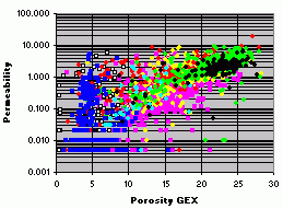
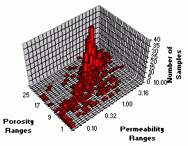
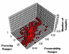
Third, a plug is not necessarily homogenous; it may include several rock-fabrics (e.g. burrows, boundstone with matrix, ...). Therefore measurements made on a heterogeneous plug should not be taken into account, even if the thin section displays only one texture. For example, plugs taken from the Rudist facies of zones "C" to "E" commonly include large shell fragments, so the matrix permeability (i.e. host rock permeability) may be grossly undervalued by conventional measurements ("Comet effect" on K/Ø frequency maps per layer or on K/Ø cross-plot: Fig. 4 ![]() ; "Manhattan effect" on 3D K/Ø histograms: Fig. 14
; "Manhattan effect" on 3D K/Ø histograms: Fig. 14 ![]() , 15
, 15 ![]() ).
).
As a matter of fact, the range of permeabilities encountered in this reservoir study is very limited; consequently this small breadth of field restricts the range in which the several rock-types can be defined. Conventional core studies and petrographical analyses available for some 5000 samples have led to the differentiation of 3 groups of lithotypes / rock-types:
Each of these three groups is comprised of 1 to 4 lithotypes.
(*): 1 Darcy = 0.9869 µm2.
The first group is made up of 4 lithotypes, the poorest in terms of reservoir characteristics:
The second group corresponds to R-chalk, i.e. a nannofossil ooze matrix with fair to high porosity, but very low permeability. It is restricted to the zone "B", i.e. layer 1.
The third group includes 2 lithotypes, the best in terms of reservoir characteristics:
The classification by layers into permeable or impermeable operational units has been set up to take into account both sequence stratigraphy (the "envelopes") and the dominant rock-type (the "contents"). In order to simplify its application (i.e. "up-scaling"), we chose a single "dominant" rock-type to characterize each layer. K/Ø cross-plots per layer (Fig. 4 ![]() ) and petrographic analyses support this preliminary rock-type classification. We note that RR measures differ slightly between zone "C" (above) and zones "D-E" (below); this is possibly related to discrete depositional environments and diagenetic overprints.
) and petrographic analyses support this preliminary rock-type classification. We note that RR measures differ slightly between zone "C" (above) and zones "D-E" (below); this is possibly related to discrete depositional environments and diagenetic overprints.
The permeability of a rock is controlled primarily by the pore-throat network, i.e. size, number, shape, and arrangement of pore-throats:
Pore-throat sizes can be estimated from the Hg injection curves (**) though these curves give only an apparent distribution ( & , 1976).
(**): E.W. (1921) first suggested the use of mercury injection as a laboratory method for determining pore throat size distribution. Assuming flow channels in the porous core sample may be represented by a bundle of straight capillary tubes in parallel with the spaces between the tubes sealed by a cementing material, the equation can be expressed as
where Pc = capillary pressure (dynes/cm2), g = surface tension of Hg = 480 dynes/cm, Q = contact angle of Hg in air = 140°; and r = radius of aperture for a cylindrical pore throat. Thus,
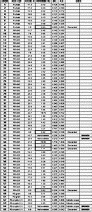
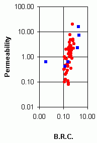
Various cross-plots using factors (***) derived from the Hg injection curves (, r35, etc.) illustrate that pore-throat size is the main factor controlling permeability (Fig. 2 ![]() ). The apparent scatter of the data is partly due to the fact that the several laboratories used divergent increments in Hg injection pressure measurements. These factors may also be involved in the way the samples are sorted (Table 1
). The apparent scatter of the data is partly due to the fact that the several laboratories used divergent increments in Hg injection pressure measurements. These factors may also be involved in the way the samples are sorted (Table 1 ![]() ).
).
(***): r35 represents the apparent radius at 35% Hg injection (, 1992) while is an weighted average radius also derived from the Hg injection curve.
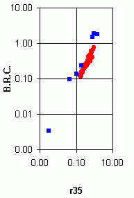
Here, 65 Hg injection curves were available (but 4 permeability measurements were missing because the corresponding plugs were broken: Table 1 ![]() ); after screening, only 7 measurements were discarded (using as a rule of thumb a >> r35: Table 1
); after screening, only 7 measurements were discarded (using as a rule of thumb a >> r35: Table 1 ![]() , Fig. 3
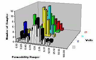
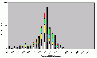
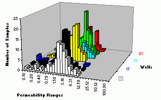
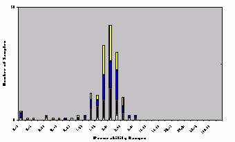
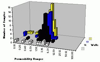
, Fig. 3 ![]() ). When considering the histograms "apparent pore-throat size" versus "apparent percentage of pore volume" per layer (Fig. 8
). When considering the histograms "apparent pore-throat size" versus "apparent percentage of pore volume" per layer (Fig. 8 ![]() , 9
, 9 ![]() , 10
, 10 ![]() , 11
, 11 ![]() , 12
, 12 ![]() , 13
, 13 ![]() ), i.e. in their relationship to the "dominant" rock-type, the following points are significant:
), i.e. in their relationship to the "dominant" rock-type, the following points are significant:
As mentioned above, there are variations within lithotype RR that may justify splitting it in accordance with the origin of the sample: zone "C" or zones "D-E". However, thin sections in carbonate rocks are usually not less than 30 µm thick; the largest pore entry radius based on the Hg injection data used in the current study never exceeds 2 µm (and rarely 1 µm ). Consequently pore throats were not visible in thin sections. Therefore permeability and porosity distributions were examined in each layer (i.e. by "dominant" rock-type).
2D histograms (Fig. 8 ![]() , 9
, 9 ![]() , 10
, 10 ![]() , 11
, 11 ![]() , 12
, 12 ![]() , 13
, 13 ![]() ) show that:
) show that:
Frequency maps and 3D histograms (Fig. 14 ![]() , 15
, 15 ![]() ) show that:
) show that:
- R-chalk ("B") K = 6.2 10-3 e0.2232Ø r2 = 0.4268 (438 samples)
- RR-"C" K = 25.6 10-3 e0.1958Ø r2 = 0.4596 (316 samples)
- RR-"D-E" K = 69.3 10-3 e0.1532Ø r2 = 0.5043 (901 samples)
where K (mD) and Ø (%).
In conclusion, RR has to be split into RR-0.45 (= RR-"D-E") and RR-0.25 (= RR-"C") which form 2 distinct rock-types. A good match was obtained with measured depth wireline log Sw using a separate "Sw versus height" equation for each rock-type:
where h (ft), Sw and Ø (fractions).
R-stylo and RR-0.45 are considered a single rock-type as the reduction in pore volume is probably restricted to the immediate vicinity of the solution seams. Presumably this reduction is accompanied only by a correlative reduction of the number of passages between pores (pore-throats). Had it been accompanied by a reduction in the size of the passages between pores, the two lithotypes would have had to remain distinct and therefore to be treated as discrete rock-types.
G.E. 's classic paper (1950) was to some extent misinterpreted. When he wrote: "The relations between rock characteristics should be thought of as trends. Actually, these may be expressed by mathematical formulae", he immediately added the following warnings: "however, the formulae can not be applied in a rigid manner (…). It must be kept in mind that appreciable deviations from the average trend may occur".
In many studies, rock-type classifications end with trendlines drawn on K/Ø cross-plots with K/Ø transforms used to predict K from either the total or the effective Ø. However statistics in this presentation show that the two ranges of data do not move together; the best fits have low coefficients of determination (r2 < 0.5). This problem was attacked with a different and promising approach: each rock-type appears to be characterized by Gaussian distributions of both log K and interparticle Ø, which as determined here almost equals the total Ø, and the two parameters are not correlated (Fig. 14 ![]() , 15
, 15 ![]() ). These distributions can serve as a basis for rock-typing. Such an approach has been used earlier to describe flow in heterogeneous media ( & , 1961). It is recommended that investigations be continued regarding its feasibility when applied to slightly more homogenous media, such as a single rock-type, and how the use of a geometric mean permeability value for a given rock-type effectively affects reservoir models and simulations.
). These distributions can serve as a basis for rock-typing. Such an approach has been used earlier to describe flow in heterogeneous media ( & , 1961). It is recommended that investigations be continued regarding its feasibility when applied to slightly more homogenous media, such as a single rock-type, and how the use of a geometric mean permeability value for a given rock-type effectively affects reservoir models and simulations.
Acknowledgements
The author thanks the Management of Abu Dhabi Marine Areas - Operation Company (ADMA-OPCO) and Abu Dhabi National Oil Company (ADNOC) for their permission (Ref. No.: E/OFFSH/SPG/530/99) granted to publish this paper on the occasion of the 9th ADIPEC (2000). Due to a large number of speakers attending the conferences the organizing committee decided to retain only one of the two papers offered by the author (the selected paper concerns the stratigraphy of the Thamama: , 2000). Subsequently the remaining paper was submitted to a foreign geoscience paper-printed journal and was accepted for publication. Two years later the journal was still not issued. Therefore it is to appear in an electronic form in "Carnets de Géologie - Notebooks on Geology". Reviews of the preliminary versions by John and Trevor resulted in many improvements to the paper. Special mention goes to Nestor J. .
G.E. (1950).- Introduction to petrophysics of reservoir rocks.- Bulletin of the American Association of Petroleum Geologists, Tulsa, vol. 34, N° 5, p. 943-961.
B. (2000).- Lower Cretaceous stratigraphy of Abu Dhabi and the United Arab Emirates - A reappraisal.- 9th Abu Dhabi International Petroleum Exhibition & Conference, Conference Proceedings, ADIPEC 0918, Abu Dhabi, October 15th-18th, p. 526-535.
F.J. (1983).- Petrophysical parameters estimated from visual descriptions of carbonate rocks: a field classification of carbonate pore space.- Journal of Petroleum Technology, Houston, vol. 35, Nº 3, p. 626-637.
T.A., J., B., M., A., A. & B. (1998).- Integrated study of a faulted and fractured reservoir.- 8th Abu Dhabi International Petroleum Exhibition & Conference, Conference Proceedings, SPE 49453, Abu Dhabi, October 11th -14th, p. 45-67.
E.D. (1992).- Relationship of porosity and permeability to various parameters derived from mercury injection-capillary pressure curves for sandstone.- Bulletin of the American Association of Petroleum Geologists, Tulsa, vol. 76, N° 2, p. 191-198.
J.E. & H.S. (1961).- Flow in heterogeneous porous media.- Society of Petroleum Engineers Journal, Houston, September 1961, p. 153-169.
N.C. & R.P. (1976).- Mercury capillary pressure curves and the interpretation of pore structure and capillary behaviour in reservoir rocks.- Bulletin of Canadian Petroleum Geology, Calgary, vol. 24, N° 2, p. 225-262.
E.W. (1921).- Note on a method of determining the distribution of pore sizes in a porous material.- Proceedings of the National Academy of Science of the United States of America, Washington, vol. 7, p. 115-116.
Click on thumbnail to enlarge the image.
Table 1: List of the available Pc curves.
Figure 1: Relationships of operational units and rock-/litho- types to reservoir layers.
Click on thumbnail to enlarge the image.
Figure 2: /K cross-plot for the 65 samples used for Hg injection. Caption: blue squares = discarded samples; red dots = remaining samples.
Click on thumbnail to enlarge the image.
Figure 3: /r35 cross-plot for the 65 samples used for Hg injection. Caption: blue squares = discarded samples; red dots = remaining samples. The program found a linear correlation between the two parameters with r35 = 1.25 + 0.07 with r2 = 0.86.
Click on thumbnail to enlarge the image.
Figure 4: K/Ø cross-plot per layer (i.e. by "dominant" rock-type). All samples with a GEX (Gas Expansion) porosity.
Click on thumbnail to enlarge the image.
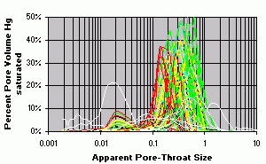
Figure 5: Hg injection data: "apparent pore-throat-size" (µm) versus "pore volume Hg saturated" (%). Key: red for R-chalk ("B"); yellow for RR-0.25 ("C"); green for RR-0.45 ("D-E"); white for discarded samples. These should be plotted as histograms; curves are used only for display!
Click on thumbnail to enlarge the image.
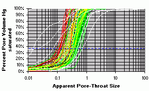
Figure 6: Hg injection data: "apparent pore-throat-size" (µm) versus "pore volume Hg saturated" (%), cumulative. Dashed horizontal line at 35% Hg injection. These should be histograms; curves are used only for display!
Click on thumbnail to enlarge the image.
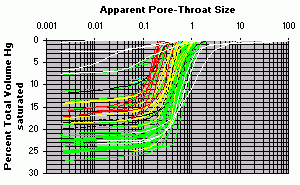
Figure 7: Hg injection data: "apparent pore-throat-size" (µm) versus "total volume Hg saturated" (%), cumulative. These should be histograms; curves are used only for display!
Click on thumbnail to enlarge the image.
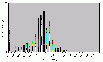
Figure 8: Permeability histogram for RR-0.25 ("C") in layer 2 (all wells).
Click on thumbnail to enlarge the image.
Figure 9: 3D permeability histograms RR-0.25 ("C") in layer 2 (each well).
Click on thumbnail to enlarge the image.
Figure 10: Permeability histogram for RR-0.45 ("D") in layer 7 (all wells).
Click on thumbnail to enlarge the image.
Figure 11: 3D permeability histograms for RR-0.45 ("D") in layer 7 (each well).
Click on thumbnail to enlarge the image.
Figure 12: Permeability histogram for RR-0.45 ("E") in layer 10 (all wells).
Click on thumbnail to enlarge the image.
Figure 13: 3D permeability histograms for RR-0.45 ("E") in layer 10 (each well).
Click on thumbnail to enlarge the image.
Figure 14: 3D K/Ø histogram for RR-0.45 ("D-E") (901 samples).
Click on thumbnail to enlarge the image.
Figure 15: As above, K/Ø scales in reverse order.